Historical context
Compact twins belong to a wider marine design history
Historical steam-engine geometry was frequently shaped by the volume available around it. ASME’s account of the two-cylinder oscillating engine on the Diesbar links its oscillating-cylinder form to a reduction in parts, material, size and weight. That particular engine is not a 90° V-twin, but it demonstrates a sound historical point: compactness was an engineering objective with consequences for linkage and maintenance.
The TV Emery Rice landmark provides a second marine example. Its horizontal compound engine was arranged at low profile for installation below a warship’s waterline, with cylinders, cranks and piston rods placed around the available space. Marine machinery therefore developed many compact configurations, selected according to hull form, shaft line, steam conditions and the requirements of the vessel rather than by a single preferred bank angle.
A 90° twin should be read with that restraint. The right angle describes the physical relationship of the cylinder banks; it does not, by itself, specify crank phase, valve timing or balance. In a model, the compact form is valuable only when steam connections, exhaust routing, lubrication and the output shaft can still be installed and inspected properly.
A bank angle is a packaging decision before it is a promise about running quality. Historical machinery shows many ways to place cylinders around a shaft, selected for the room available, the form of the driven machinery and the service conditions. It is therefore more accurate to ask what a particular V layout permits an installer to do than to present a right angle as a universal answer to balance, starting or steam distribution.
Engineering principle
Right-angle packaging and crank phasing
A 90-degree twin places its cylinder banks at right angles. That geometric choice can concentrate two cylinders into a short installation envelope, but it does not establish its cranktrain phasing. Torque regularity requires separately selected crank and valve phase; the benefit comes from that time relationship rather than from the external V shape alone.
The compact envelope heightens the importance of steam passages, exhaust routing and access for oiling. Shorter external dimensions are useful only when the installation still permits unrestricted linkage motion, a rigid mounting surface and a truly aligned output shaft.
Bank angle and crank phase are separate variables. The bank angle describes the physical angle between cylinder centre lines; crank phase describes the angular relationship of the throws on the crankshaft. They may be selected to work together in a particular engine, but neither quantity can be deduced safely from the other. Valve timing adds a third time-based relationship, because admission and exhaust events determine when each cylinder can use its crank position.
The installation envelope is more than an outline around the engine. It includes room for the moving rods and valve gear, clearance for steam and exhaust connections, a route for lubrication, access to fasteners and a coupling path to the driven shaft. A compact layout can lose its practical advantage if it forces a sharp pipe bend, blocks an oil point or places the output coupling under side load.
Design trade-offs
V-twin trade-offs: compact form must remain serviceable
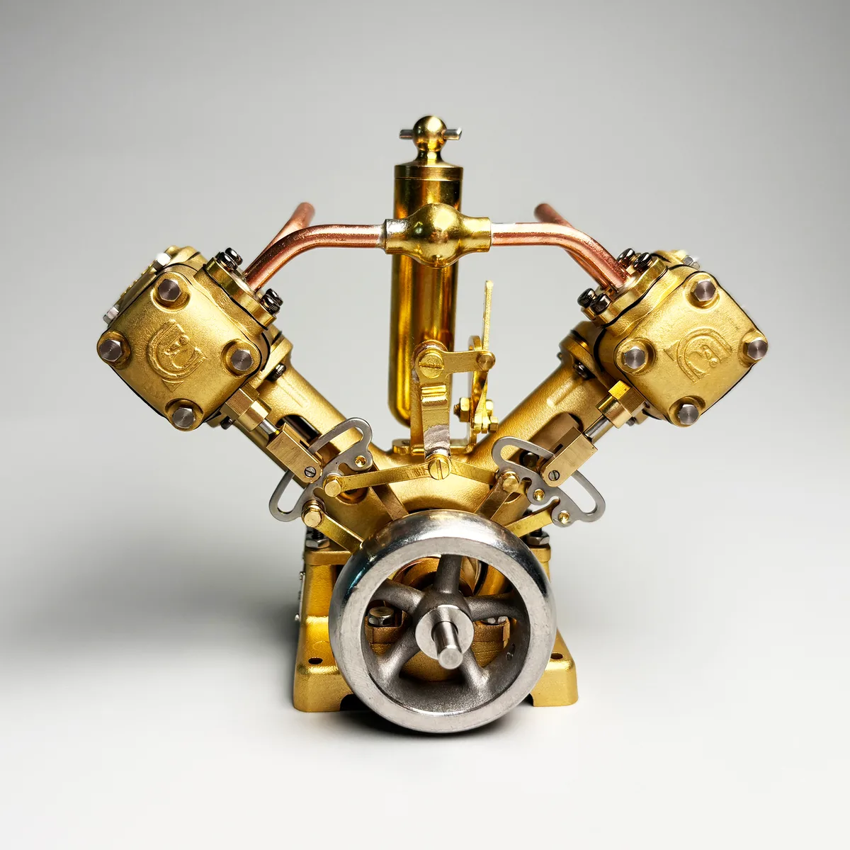
A right-angle twin can place two cylinders around a common crankshaft without extending the mechanism along one long centreline. That can be useful when the surrounding installation has limited length or when an exposed V shape is part of the intended display. The compactness is a layout benefit, not a statement about the steam system: each cylinder still needs clear steam supply, exhaust flow, lubrication and correctly timed valve action.
The price of close packaging is that access must be designed or planned carefully. A model engineer should be able to reach oiling points, observe the motion of both banks and remove or adjust external connections without loading the mechanism. The mount needs enough stiffness to hold the output shaft in line, because a short engine does not make a misaligned coupling less consequential.
A V form may also change what can be seen during diagnosis. The two banks make a useful comparison point—one can look for consistent rod motion and valve response—but the central space can be more crowded than in an inline engine. Selection should therefore begin with the actual installation envelope and the desired maintenance access, not only with the visual appeal of the bank angle.
The right way to judge compactness is with the engine installed, not on a clear bench. Confirm that the controls can be reached, the coupling can be aligned, the steam connection can be inspected and the exhaust route does not obstruct motion. If any of those tasks require removing unrelated parts, the practical benefit of a small footprint may be outweighed by reduced serviceability.
A well-planned V-twin installation can therefore be compact without being cramped. Allow a deliberate service zone around the controls and the moving linkage, and treat pipe runs and couplings as part of the mechanism’s layout. This preserves the benefit of the bank angle while leaving the owner able to inspect and maintain the engine as a working machine.
This is particularly useful in a model boat or enclosed display where every external connection competes for space. Planning the installation envelope before fastening the engine prevents a compact internal arrangement from becoming an inaccessible one after the steam and drive connections are made.
Collector's perspective
Collector’s perspective: distinguish geometry from timing
A V-twin is most rewarding when it is viewed as two related geometries. The cylinder banks establish the external right-angle form; the crankshaft and valve gear establish the sequence of motion. At a controlled speed, watch the two pistons and connecting rods pass through different parts of their strokes. This makes the distinction between the V shape and the phasing of the mechanism immediately tangible.
Look for practical workmanship around the compact core: clean routing of steam connections, no interference through the full stroke, supports that hold the shaft without obvious movement and sufficient access to lubrication. These details matter more than a generic claim that a V arrangement is automatically smoother or more balanced than any other twin.
For collection care, preserve the access that makes inspection possible. Avoid mounting a compact engine so tightly that its reverse linkage, oil points or coupling cannot be reached. A display that leaves the operating sides visible supports both historical appreciation and the disciplined preparation needed before a live-steam run.
Documented implementation
The documented V2 implementation
Rocking Whale identifies the V2 as a 90-degree twin-cylinder engine. The V2/L2 manual describes a die-cast brass engine structure, stainless-steel cylinder liners, composite piston rings, a ball-bearing-supported crankshaft, precision CNC-machined parts and complete Stephenson valve gear for forward and reverse.
The V2 is documented at 6 cc displacement, 3000 RPM, 1200 gf·cm maximum torque and 0.03 HP. Its normal working-pressure range is 0.5–2 bar, and engine working pressure must not exceed 3 bar.
Operational practice
Working within the documented limits
Lubricate the oil tank and all specified rotating and moving parts before operation; drain accumulated water from the oil tank first. The manual calls for a running-in period of about one hour below 2000 RPM, after which fasteners should be checked. It does not recommend prolonged operation on compressed air because steam cylinder oil cannot enter the engine in that mode.
Run the engine only on a flat mounting plate with the driven shaft concentric to the crankshaft. Reduce speed before moving the reversing gear, and avoid high speed without load. The engine and its exhaust steam are hot during and after operation; allow cooling time before handling.
Documented figures
Model-specific specifications.
| Specification | Documented value |
|---|---|
| Configuration | 90° twin-cylinder |
| Displacement | 6 cc (1.5 cc × 2 × 2) |
| Speed | 3000 RPM |
| Maximum torque | 1200 gf·cm |
| Power | 0.03 HP |
| Normal working pressure | 0.5–2 bar |
| Maximum working pressure | 3 bar |
Editorial sources
References & further reading
- Oscillating Steam Engine American Society of Mechanical Engineers Open source
- TV Emery Rice Steam Engine American Society of Mechanical Engineers Open source
Engineering tools & resources
Comparing engine configurations? Explore the Model Steam Engine Comparison Guide. Evaluating hull propulsion? Use the interactive Model Boat Steam Engine Size Calculator.