
Historical context
Working models are a record of mechanical ideas
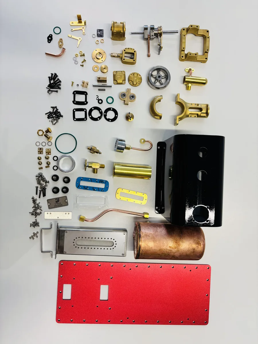
A working steam model is not simply a reduced object. It is a compact way of preserving the relationships that make a reciprocating engine intelligible: a pressure vessel, admission and exhaust passages, a piston, a connecting rod, a crank and an external load. The Science Museum Group catalogues model steam engines alongside full-scale motive-power objects, including a London-made model and a workshop model built by engineering apprentices.
This connection to practice matters. A model can reveal motion that would be hidden inside a large engine house or hull, while still demanding the same disciplined distinction between heat source, pressure system, valve events and rotating mechanism. It is therefore useful to treat a working model as an engineering demonstrator rather than as a miniature that excuses simplified reasoning.
The historical record includes models made for display, instruction, patent communication and workshop culture. The Science Museum Group’s apprentice-built beam-engine workshop, for example, was designed so miniature machine tools could move from a belt drive. That is a reminder that models have long been used to make power transmission and mechanism visible, not merely decorative.
That demonstrator role is especially valuable because it joins several scales of history. A small working model lets a learner follow the path from heat to pressure and from piston travel to shaft rotation without losing sight of the complete plant. It does not make a model a direct scale replica of a mill engine or a ship installation. Rather, it makes selected engineering relationships available for inspection, adjustment and discussion.
The best historical reading of a model starts with its purpose. Some models explain a mechanism in a classroom or museum; some preserve the appearance and movement of a particular engine family; others are designed as self-contained working models for a bench, a launch or a display. These purposes overlap, but they call for different standards of fidelity. A model intended to run must reconcile steam supply, lubrication, clearances and safety with an envelope far smaller than the original installation.
Historical context
From atmospheric pumping to rotary power
Early practical steam engines were closely tied to pumping and other stationary duties. ASME identifies the Newcomen steam-atmospheric engine of about 1712 as a foundational practical thermal prime mover. Its reciprocating motion was valuable in its own right, but later machinery often required continuous rotary motion at a shaft.
The Boulton & Watt rotative engine designated by ASME shows an important part of that transition. Its mechanism connected a reciprocating engine to shaft rotation, while the associated separate condenser, parallel motion, governor and double-acting development illustrate why the steam engine should be read as a coordinated system rather than as a cylinder alone.
For the model engineer, this lineage clarifies why the flywheel, crank, valve gear and regulator attract attention. Each has a mechanical role in storing energy, converting direction of motion, controlling steam events or managing operating speed. A small live-steam plant makes those roles observable at one bench rather than across an engine house.
Stationary applications make this sequence easy to read: an engine receives steam, turns a shaft and transmits motion to a pump, line shaft, generator or workshop load. Marine applications add the constraint of an enclosed hull, propeller shaft and changing resistance in water. Historical engine builders responded with many arrangements, from compact machinery below deck to engines intended for direct shaft drive. The point is not that every model repeats those applications, but that they explain why access, mounting and shaft line have always been engineering concerns.
Engineering principle
Why cylinder arrangements multiplied
A single cylinder gives the clearest view of the complete pressure-to-motion path, but it also has crank positions with little turning leverage. Adding cylinders provides additional opportunities for torque during a revolution when their cranks and valve events are appropriately arranged. That principle explains the move from single-cylinder demonstrations to twins and compact multi-cylinder engines without claiming that one arrangement automatically solves every balance or starting problem.
The following articles use that progression as an engineering map: the single-cylinder engine and boiler as a complete plant; the generic twin as a study in phasing; the inline twin as an exposed, aligned mechanism; the 90° twin as a compact package; and the V4 as a coordinated multi-cylinder assembly. The layouts are not a ladder of universal superiority: their value depends on duty, steam supply, access, mounting and the design of their valve gear.
Full-size history also supplies context for this variety. ASME documents horizontal compound marine engines shaped by the need to fit machinery below a ship’s waterline, and later marine-type engines adapted to stationary generating work. The same broad engineering questions—space, shaft arrangement, controllability and serviceability—remain meaningful when a model is selected for a launch, display stand or workshop demonstration.
Cylinder layouts should therefore be compared as systems. A single-cylinder engine makes the basic conversion unusually easy to see. A twin can distribute torque events through the revolution. Inline and V arrangements package those cylinders differently, while four-cylinder engines make the coordination of crankshaft, valve gear and steam paths more prominent. The following articles use working models to examine those choices without treating the historical development as a straight line from “simple” to “better.”
Working models are particularly good at exposing the boundary between a general principle and a design decision. Every reciprocating steam engine has to admit and exhaust steam, convert piston force through a crank and support a rotating shaft. Whether it needs a long base, a compact bank angle, more than one cylinder or a particular form of reversing gear depends on its intended duty and construction. Reading a model in this way makes the historical narrative more useful: it becomes a guide to questions, not a catalogue of claims to repeat.
Editorial sources
References & further reading
- Model steam engine Science Museum Group Collection Open source
- Model beam engine and workshop made by ICI apprentices Science Museum Group Collection Open source
- Boulton & Watt Rotative Steam Engine American Society of Mechanical Engineers Open source
- The Newcomen Steam-Atmospheric Engine American Society of Mechanical Engineers Open source
- TV Emery Rice Steam Engine American Society of Mechanical Engineers Open source
Engineering tools & resources
Comparing engine configurations? Explore the Model Steam Engine Comparison Guide. Evaluating hull propulsion? Use the interactive Model Boat Steam Engine Size Calculator.