Historical context
The historical development of link motion and variable expansion
During the rapid expansion of railway motive power in the 1840s, engineers sought a robust mechanical system capable of both reversing locomotive direction and adjusting steam cut-off during running. The Science Museum Group documents early model engines equipped with dual-eccentric link motions, demonstrating how apprentice workshops and mechanical institutes preserved the geometry pioneered by Robert Stephenson and William Howe. Prior to link motion, reversing commonly required cumbersome slip-eccentrics, gab motions, or separate forward and backward valve chests that could not alter expansion stages continuously.
The Stephenson link motion solved these challenges by combining two separate eccentrics keyed to the main shaft with a curved slotted link. By suspending this expansion link from a weigh-shaft and reversing quadrant, a driver or operator could shift the die block from full forward gear through mid-gear to full reverse gear. The intermediate positions reduced valve travel, effecting earlier cut-off and harnessing the expansive property of steam to save fuel and water on long runs.
In working scale models, the mechanism preserves this elegant kinematic relationship on a visible benchtop scale. The miniature valve gear allows students and model engineers to observe how small rotational offsets at the crankshaft translate into linear reciprocating valve events at the cylinder steam chest. Rather than treating valve gear as an abstract schematic, a functioning model demonstrates the direct mechanical linkage connecting heat expansion to rotational shaft work.
Historical marine installations also adopted link motion extensively for harbor launches, paddle steamers, and tugboats where rapid and reliable manoeuvrability was paramount. While modern full-size marine propulsion has evolved toward internal combustion and electrical drives, live-steam model engineering remains the preeminent living archive of these foundational kinematic mechanisms.
Engineering principle
Kinematics of dual eccentrics, expansion links, and valve travel
The fundamental operating principle of Stephenson link gear relies on two eccentrics mounted with specific angular advance on the crankshaft. For an engine with an outside-admission D-slide valve, each eccentric is set at 90 degrees plus an angle of advance ahead of the respective crankpin direction. This angular advance provides the necessary valve lap and lead, ensuring that the steam port is already cracked open by a small, controlled amount when the piston reaches top dead centre or bottom dead centre.
The curved expansion link connects the ends of the forward and backward eccentric rods. Its curvature is machined to a radius equal to the length of the eccentric rod measured from the eccentric strap centre to the link pin. This specific radius ensures that when the link is shifted between forward and reverse, the valve lead remains substantially constant at both dead centres, preventing unwanted timing shifts as the reversing lever moves across the quadrant.
When the die block resides at the extreme top of the link, the valve takes its reciprocating motion almost exclusively from the forward eccentric rod, providing maximum port opening and late cut-off for high starting torque. As the link is raised toward mid-gear, the resultant motion imparted to the valve decreases in amplitude, causing the valve to close the admission port earlier in the piston stroke while maintaining continuous compression and exhaust release events.
Kinematic symmetry between the forward and backward eccentric rods is essential for balanced power delivery. If eccentric sheaves are machined with unequal throws or if eccentric rods differ in length, the engine will suffer asymmetrical admission timing between forward and reverse running. Precise measurement of valve travel and lead at both dead-centre positions ensures balanced mean effective pressure across both cylinder ends.
Design trade-offs
Mechanical trade-offs: link motion versus single fixed eccentrics
Selecting Stephenson valve gear over simpler arrangements involves deliberate engineering trade-offs. A simple single-cylinder engine with a fixed or slip eccentric requires only one sheave, one rod, and minimal pivots, making it compact and inexpensive to produce. However, a slip eccentric cannot alter expansion during running and requires shaft rotation to initiate reversing, making it unsuitable for radio-controlled boat maneuvering or remote throttle management.
Stephenson link motion introduces eight or more precision pivot points per cylinder, including eccentric strap bearings, fork joints, link die blocks, suspension links, and reach-rod connections. In miniature live-steam construction, any radial play or backlash across these joints accumulates at the valve spindle, resulting in lost motion that distorts port opening and valve timing.
Lubrication access is another critical trade-off. The open geometry of curved links and rocker arms exposes moving joints to external oiling, requiring frequent application of compounded steam oil. Enclosed rotary valves or modern poppet mechanisms may offer sealed operation, but they obscure the visible mechanical action that defines traditional steam demonstrator models.
Fabrication tolerances must remain exceptionally tight. Machining the curved slot of the expansion link and fitting a bronze die block requires careful milling and hand lapping. When executed with precision, the mechanism delivers crisp reversing authority and smooth running that repays the additional manufacturing complexity.
Collector's perspective
Collector’s perspective: observing quadrant travel and link motion
For the dedicated model collector and enthusiast, a steam engine equipped with Stephenson link motion is a masterpiece of kinetic sculpture. Watching the two eccentric rods oscillate in opposite phase while the suspension link guides the curved slot creates a visual rhythm that captures the golden age of mechanical engineering. The movement transforms invisible steam thermodynamics into observable geometric motion.
When inspecting a model, examine the quadrant lever mechanism and the suspension link bearings. High-grade models exhibit crisp detent action at full forward, mid-gear, and reverse settings, with zero binding across the arc of movement. Rotating the flywheel slowly by hand reveals how the die block floats inside the curved slot while transferring decisive reciprocating stroke to the valve spindle.
Preserving this intricate linkage requires clean operating conditions and disciplined maintenance. After live steaming, wiping away condensate droplets, lubricating all clevis pins, and applying a light protective oil film prevents corrosion and preserves the fine polished finish of brass and steel components for generations of display.
Documented implementation
Stephenson valve gear on the documented Rocking Whale V2
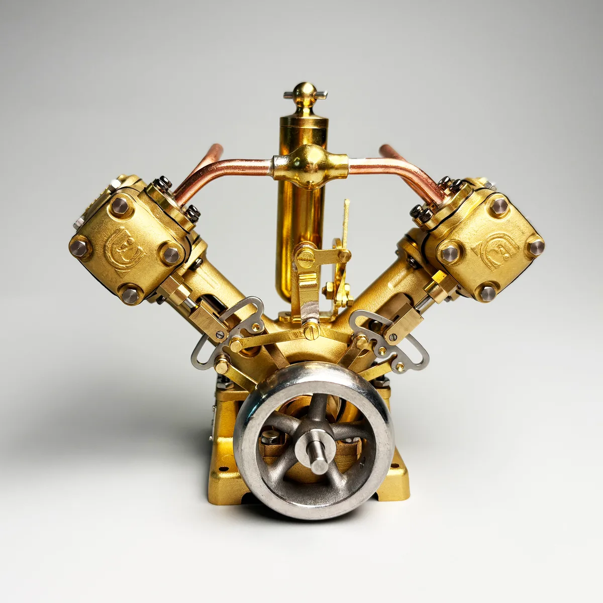
Rocking Whale documents the V2 as a 90° twin-cylinder model steam engine featuring a complete Stephenson reversing link mechanism. The engine pairs precision CNC-machined brass linkage arms and dual eccentric sheaves on each cylinder line, providing fully independent reversing control across its twin cylinder banks.
The V2 is documented with a 3000 RPM operating speed, 1200 gf·cm maximum torque, and a normal working-pressure range of 0.5–2 bar with a 3 bar maximum pressure limit. The documented valve gear provides crisp direction changes and balanced steam distribution across the 90° cylinder layout.
Operational practice
Setting valve lead, synchronisation, and workshop procedure
Timing Stephenson valve gear begins by establishing true top dead centre and bottom dead centre on the engine crankshaft. With the cylinder steam chest cover removed, place the reversing lever in full forward gear and rotate the shaft in the running direction until the piston reaches top dead centre. Observe the edge of the slide valve relative to the upper admission steam port.
Adjust the valve spindle length by rotating its threaded clevis until the port reveals the specified lead opening—typically 0.2 mm to 0.4 mm on miniature engines. Rotate the flywheel 180 degrees to bottom dead centre and verify that the opposite steam port reveals an identical lead opening. Symmetrical lead confirms that the valve spindle length is correctly centered.
Next, move the reversing lever to full reverse gear and rotate the shaft in the opposite direction, verifying that identical lead appears at both dead centres. If lead is asymmetrical in reverse, adjust the angular advance of the reverse eccentric sheave on the crankshaft before locking its grub screws. Finally, test the mechanism under 0.5 bar low-pressure compressed air to confirm smooth, self-starting rotation in both directions before introducing live steam.
Documented figures
Model-specific specifications.
| Specification | Documented value |
|---|---|
| Configuration | 90° twin-cylinder |
| Speed | 3000 RPM |
| Max. torque | 1200 gf·cm |
| Normal working pressure | 0.5–2 bar |
| Maximum working pressure | 3 bar |
Editorial sources
References & further reading
- Boulton & Watt Rotative Steam Engine and Valve Gear American Society of Mechanical Engineers Open source
- Model steam engine with Stephenson link motion Science Museum Group Collection Open source
Engineering tools & resources
Comparing engine configurations? Explore the Model Steam Engine Comparison Guide. Evaluating hull propulsion? Use the interactive Model Boat Steam Engine Size Calculator.