Historical context
Inline mechanisms and the stationary-engine tradition
An inline arrangement places cylinders with parallel axes in a straight row along the crankshaft, making the path from piston rod to crankshaft easy to inspect. That visual legibility echoes the long history of stationary engines, where operators had to observe bearings, rods, valve gear and belt-driven loads in service. ASME’s Harris-Corliss landmark records a late nineteenth-century engine used to drive machinery through overhead line shafting, an example of an engine as part of a visible power-transmission system.
The history of stationary steam does not prescribe one inline form. It does show why a rigid foundation, accessible lubrication points and understandable linkage were valuable. The New England Museum of Wireless and Steam collection, recognised by ASME, preserves engines ranging across Rhode Island manufacturing history and includes models as well as full-size engines; that breadth is a useful warning not to collapse all exposed mechanisms into one historical type.
For an inline twin model, the most instructive historical connection is therefore operational rather than genealogical. The straight, visible layout rewards careful observation of centreline alignment, bearing condition and valve motion. Those are the same categories of attention that distinguished a dependable engine installation from a merely attractive one.
Marine applications offer a complementary comparison. A ship’s engine still requires a clear relationship between its cylinders, crankshaft and propeller shaft, even when the surrounding hull makes access more constrained than in an engine house. Inline machinery is not the only marine form, but the history of marine installations reinforces why shaft alignment, secure bearing support and service access are practical concerns rather than workshop niceties.
Engineering principle
An inline arrangement makes the mechanism legible
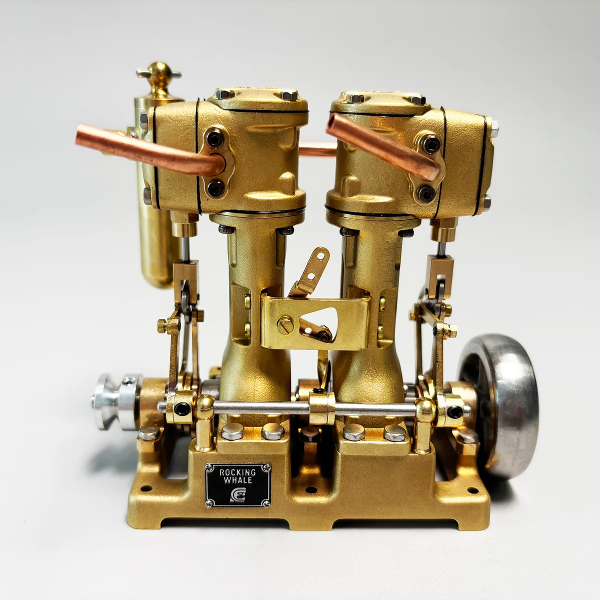
In an inline twin, the cylinders are arranged with parallel axes in a straight row along the crankshaft. The layout presents rods, crossheads and valve gear clearly, which makes it especially useful for observing motion and for inspecting the relationship between frame alignment and shaft alignment. Crank phase is determined by the specific crankshaft and valve arrangement, and should not be inferred from the inline form alone.
Visibility does not reduce the need for precision. A small offset between engine and driven shaft can introduce cyclic side loads, raise bearing friction and make an otherwise sound engine appear uneven. The foundation must be flat and sufficiently rigid to preserve the engine frame geometry.
Bearing support is part of that geometry. Bearings locate the crankshaft while allowing it to rotate, and the frame or bearing housings must keep their centres in a stable relationship under load. The number, placement and construction of bearings are design-specific matters; the general principle is that support must resist unwanted shaft displacement without introducing binding. An inline layout makes any departure from the intended line of action relatively easy to see, but not necessarily easy to correct after mounting.
The visible mechanism should not be mistaken for a universally identical valve arrangement. The cylinder axes, crank phase, rod length and valve gear are selected together by a particular designer. An inline label describes packaging. It does not reveal whether an engine is compound or simple, its valve events, its steam consumption, or a particular performance figure.
Design trade-offs
Inline trade-offs: access, shaft line and alignment
The inline form is attractive where the observer or engineer values a long, open view of the rods, crankpins and valve gear. That accessibility can simplify visual checks, lubrication and explanation. It can also make a model look at home on a stationary display base, where the mechanism rather than a compact enclosure is the principal object of interest.
The same straight layout can make installation alignment unforgiving. The engine shaft, coupling and driven shaft must share a practical centreline, while the mounting plate must not distort the frame when fastened down. A flexible plate, an angled coupling or a driven shaft that pulls sideways can transfer load into the bearings and conceal the cause behind an apparently uneven rotation.
Packaging is therefore a choice rather than an automatic advantage. The longitudinal form may suit a display, a hull or a line-shaft arrangement that has length available, while a V layout may be more appropriate where width and height can be traded for a shorter run. Neither form alone tells the engineer how much steam a given installation will require.
An inline installation should be planned from the shaft line outward. Establish a level, rigid base; place the driven component so its coupling does not pull the crankshaft sideways; then confirm that the mechanism remains accessible once pipework and guards are fitted. This order prevents a common mistake in model installations: treating the engine as correctly mounted because its feet are fastened down, even though the connected shaft is defining an unintended line of action.
This attention to the mounting sequence pays off when troubleshooting. If an inline mechanism turns freely before coupling but grows stiff afterwards, the installation has supplied evidence: the problem may lie in the shaft line or base rather than in the cylinders themselves. Separating those possibilities is a basic engineering habit and one of the layout’s practical advantages.
The long visible arrangement also makes wear easier to localise. A change in rod motion, a dry bearing or a loose support can often be seen before it becomes a serious running issue. That visibility does not replace measured inspection, but it gives the owner a clear starting point for responsible maintenance.
Collector's perspective
Collector’s perspective: follow the line of action
An inline twin rewards slow observation. From the cylinder faces, follow each piston rod through its guides and connecting rod to the crankshaft, then look along the bearing supports toward the output. This path explains why an inline engine can be such an effective working model: the conversion from reciprocation to rotation is visibly ordered rather than hidden between cylinder banks.
The most satisfying examples show discipline in the ordinary details—square mounting faces, freely moving linkage, accessible oiling points and a shaft that appears to turn without a lateral wander. These are not cosmetic traits. They are evidence that the visible mechanism has been treated as a working assembly rather than a collection of separately finished parts.
Collectors should preserve that legibility. Keep the model clean enough that oil ports, fasteners and bearing locations can be inspected, and do not use a display arrangement that loads the output shaft sideways. A model that can be understood at rest is easier to appreciate and safer to prepare for operation.
Documented implementation
The documented L2 implementation
Rocking Whale documents the L2 as an inline twin-cylinder engine with a die-cast brass structure, stainless-steel cylinder liners, composite piston rings, CNC-machined parts and complete Stephenson reversing gear. Its crankshaft is supported by six ball bearings, a detail that supports its stated smooth and stable running character.
The L2 is documented at 6 cc displacement, 3000 RPM, 1200 gf·cm maximum torque and 0.03 HP. The manual specifies a normal working-pressure range of 0.5–2 bar and a maximum of 3 bar.
Operational practice
Alignment, lubrication and reversing
Install the L2 on a flat wood or metal plate and set the driven shaft concentric with the engine shaft, as the manual directs. Before operation, charge the oil tank with steam oil, lubricate the moving parts and drain condensed water from the tank. The manual recommends about one hour of running-in below 2000 RPM and periodic checks for loose fasteners and wear.
Reduce speed before changing the Stephenson reverse setting. No-load overspeed should be avoided; the documented maximum working speed is 3000 RPM. Treat the stated pressure and speed values as limits for the L2, not as substitutes for matching boiler, piping and propeller load to the installation.
Documented figures
Model-specific specifications.
| Specification | Documented value |
|---|---|
| Configuration | Inline twin-cylinder |
| Displacement | 6 cc (1.5 cc × 2 × 2) |
| Speed | 3000 RPM |
| Maximum torque | 1200 gf·cm |
| Power | 0.03 HP |
| Normal working pressure | 0.5–2 bar |
| Maximum working pressure | 3 bar |
Editorial sources
References & further reading
- Harris-Corliss Steam Engine American Society of Mechanical Engineers Open source
- Steam engine collection New England Museum of Wireless and Steam via ASME Open source
Engineering tools & resources
Comparing engine configurations? Explore the Model Steam Engine Comparison Guide. Evaluating hull propulsion? Use the interactive Model Boat Steam Engine Size Calculator.