Historical context
The engineering necessity of steam-cylinder lubrication
Throughout the history of industrial steam power, the effective lubrication of cylinders, piston rings, and valve faces has presented unique tribological challenges. Unlike internal combustion engines where oil circulates in dry crankcases, a steam engine operates under continuous exposure to high-temperature saturated steam and hot condensate. Standard mineral motor oils emulsify rapidly or wash off cylinder walls, leading to metal-to-metal scuffing, severe blow-by, and irreversible bore damage.
Historic marine and locomotive engineering overcome this problem by formulating specialized compounded steam cylinder oils. These lubricants combine high-viscosity mineral base stocks (typically ISO VG 460 or ISO VG 680) with a small percentage of fatty oils, such as tallow or synthetic esters. When atomized in the steam supply line, the fatty additives create a persistent, water-resistant emulsion that clings tenaciously to wet cylinder surfaces even under high steam velocity.
Apprentice training programs documented by the Science Museum Group placed heavy emphasis on correct oiling rituals and mechanical inspection before starting any live-steam plant. Apprentices learned that a well-lubricated miniature engine could run reliably for decades, whereas a dry start under live steam could score precision brass and stainless steel surfaces within minutes.
Understanding the distinction between internal steam-path lubrication and external bearing lubrication remains the cornerstone of live-steam ownership. Internal parts require compounded steam oil delivered via displacement lubricators, while external crankshaft bearings, crossheads, and eccentric straps require light machine oil with low viscous drag.
Mechanical cleanliness during workshop storage and running preparation forms the foundation of reliable performance. Any dust, lint, or abrasive grit introduced into open oil holes will quickly embed in soft bronze bushings and score polished steel journals. Maintaining a dedicated lint-free wiping cloth and covered oil containers prevents contamination from entering miniature bearing surfaces.
Engineering principle
Hydrodynamic films, gland packing friction, and thermal expansion
The primary objective of mechanical break-in is the controlled bedding-in of sliding surfaces to establish continuous hydrodynamic oil films. Freshly machined bronze pistons, composite rings, and stainless steel cylinder liners possess microscopic surface peaks and valleys. During the initial running-in phase under light load, these asperities gently burnish into conforming, mirror-smooth contact surfaces without tearing or localized overheating.
Piston rod gland packings represent a major source of parasitic friction if improperly adjusted. Traditional packing materials, such as graphited PTFE yarn or silicone O-rings, rely on controlled compression to seal steam pressure. Overtightening the gland nut creates excessive clamping force on the rod, stalling small engines and accelerating rod wear. An ideally adjusted gland allows slight initial weeping of condensate during warm-up until thermal expansion achieves a tight, low-friction dynamic seal.
Displacement lubricators operate through hydrostatic condensation. Saturated steam enters the lubricator vessel and condenses against the cool metal walls. Because water has a higher specific gravity than steam cylinder oil, the condensed water sinks to the bottom, displacing an equivalent volume of oil out through the delivery nozzle into the steam supply stream. Maintaining this continuous micro-feed prevents cylinder starvation throughout a running session.
Thermal expansion differentials between brass engine frames, bronze pistons, and steel rods must also equalize during warm-up. Running the engine at reduced pressure during the first ten minutes allows all components to reach thermal equilibrium before demanding full shaft output.
Crankshaft journal alignment and big-end bearing clearances dictate how freely an assembled engine will turn over by hand. If connecting rod split bearings are clamped too tightly around the crankpins, the resulting boundary friction will absorb a significant portion of indicated steam power before it ever reaches the output coupling.
Design trade-offs
Material pairing, tolerance choices, and break-in dynamics
Engine designers must balance tight mechanical clearances against the risk of thermal seizure during early operation. Selecting dissimilar metals—such as brass or bronze sliding against stainless steel—minimizes galling tendencies under steam heat. However, bronze exhibits a higher coefficient of thermal expansion than steel, meaning cold assembly clearances must accommodate growth at operating temperatures above 100°C.
A common mistake among beginners is attempting high-speed runs or heavy torque loading immediately after unboxing a new model. Under high load, unseated piston rings generate localized friction heat faster than the lubrication film can dissipate, creating hot spots that degrade surface hardness and compromise cylinder compression.
Piston ring material selection also influences break-in duration. Traditional cast-iron rings require extensive running-in against cast liners, whereas modern composite PTFE-graphite rings bed in rapidly and offer low breakout friction. However, composite rings still require disciplined lubrication to prevent particulate buildup in ring grooves.
The trade-off between tight compression sealing and effortless mechanical spinning is resolved through patient break-in. An engine that is properly run in develops superior compression and turns over with silky smoothness, starting reliably on gentle initial steam pressure without requiring manual flywheel flicking.
Fastener tension across cylinder covers and bearing caps must be monitored closely during initial thermal cycles. As brass and bronze castings heat and expand, threaded fasteners can experience differential expansion stresses. Checking screw tightness after the engine cools down ensures steam-tight joints without stripped threads.
Collector's perspective
Preservation practices, patina care, and long-term storage
Post-run maintenance is what separates engines that endure for generations from those that suffer internal corrosion. When a live-steam session ends, cooling steam inside cylinders and boilers condenses into standing water. If left unserviced, acidic condensate reacts with brass, bronze, and steel fasteners, seizing piston rods and forming unsightly green verdigris.
Immediately following a steaming session, drain all water from the displacement lubricator and cylinder drain cocks. While the engine remains warm, connect a low-pressure air supply and spin the mechanism for two minutes to expel all residual moisture from steam passages and exhaust manifolds.
Introduce several drops of light machine oil directly into the steam inlet and turn the flywheel over by hand to coat internal bore surfaces. Wipe external brasswork with a soft microfiber cloth lightly misted with paraffin or neutral mineral oil. This disciplined routine preserves the lustrous golden patina of polished brass while protecting precision sliding fits during long-term display.
Display environments should be dry, well-ventilated, and free from corrosive fumes or excessive humidity. Storing a live-steam demonstrator model under a clear acrylic or glass dust cover shields precision linkage joints from atmospheric grime while showcasing the engine as a centerpiece of mechanical art.
Documented implementation
Lubrication and maintenance on the documented Rocking Whale L2
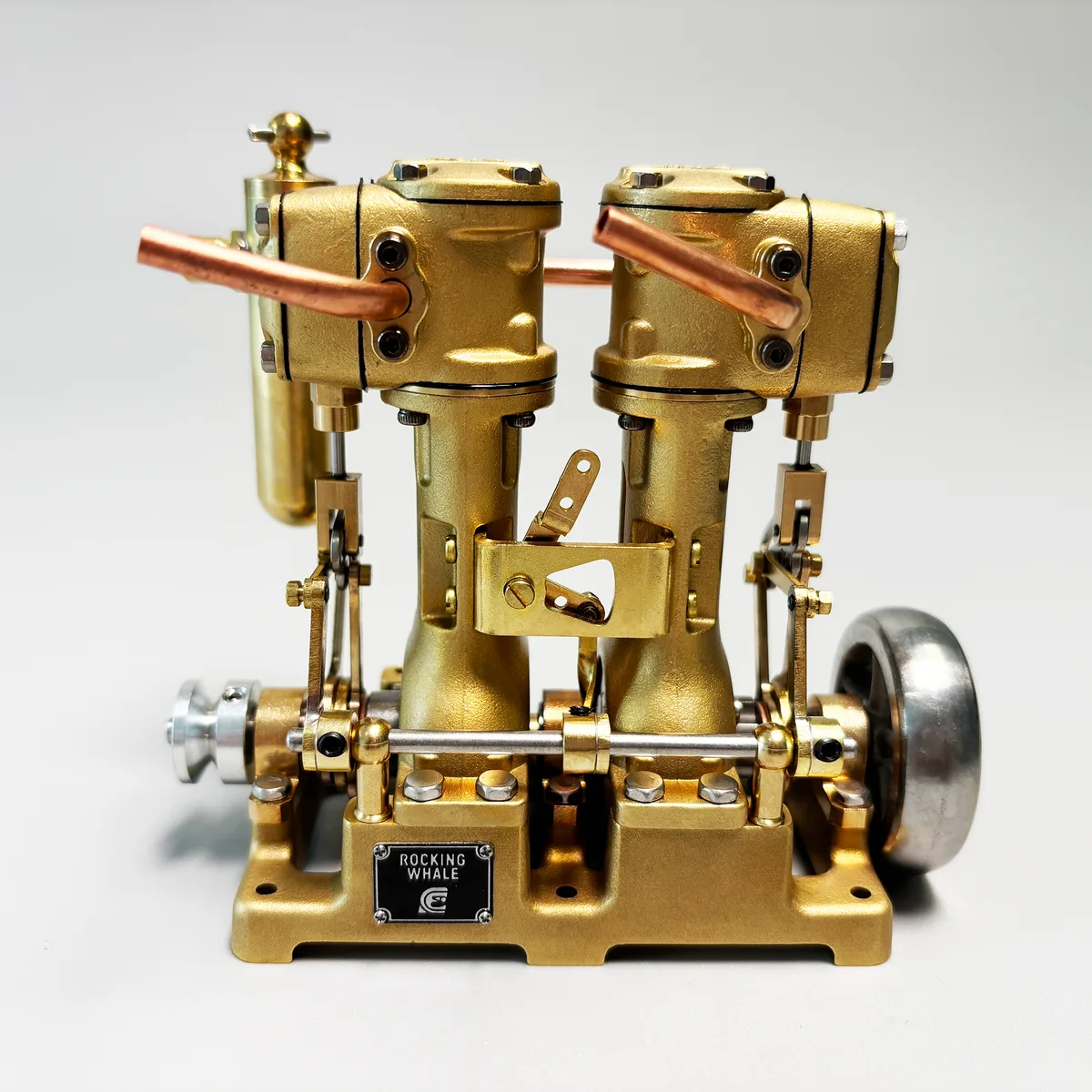
Rocking Whale documents the L2 as an inline twin-cylinder model steam engine built with an open, visible mechanical architecture. The engine features six ball-bearing crankshaft supports, CNC-machined brass components, stainless-steel cylinder liners, and an integrated displacement oiler designed for continuous steam-stream lubrication.
Documented specifications for the L2 include an operating speed of 3000 RPM, 1200 gf·cm maximum torque, a normal working-pressure range of 0.5–2 bar, and a maximum working pressure of 3 bar. The open inline layout provides direct visual and physical access to all bearing journals, connecting rod big-ends, and valve gear clevis points.
Operational practice
Step-by-step break-in schedule and pre-steaming checks
Prior to the initial run, apply a drop of light machine oil to every external bearing journal, crosshead guide, and eccentric strap. Fill the displacement lubricator vessel with ISO VG 460 compounded steam cylinder oil and tighten the filler cap securely. Verify by hand that the flywheel spins completely freely through 360 degrees without tight spots.
Conduct the initial break-in session on a workshop bench using clean compressed air regulated to gentle low pressure. Run the engine at a gentle speed below 1500 RPM for 30 to 45 minutes, periodically applying external oil to all pivots. This gentle bench run allows piston rings, crossheads, and crankpins to burnish their working surfaces without thermal stress.
Following the air break-in, inspect all grub screws, bearing caps, and cylinder head fasteners for tightness. When transitioning to live steam, allow the boiler to reach working pressure before cracking open the steam regulator slowly. Discard the initial emulsified condensate from the exhaust and verify that a fine mist of cylinder oil lubricates the piston rods throughout the run.
Documented figures
Model-specific specifications.
| Specification | Documented value |
|---|---|
| Configuration | Inline twin-cylinder |
| Speed | 3000 RPM |
| Max. torque | 1200 gf·cm |
| Normal working pressure | 0.5–2 bar |
| Maximum working pressure | 3 bar |
Editorial sources
References & further reading
- TV Emery Rice Steam Engine and Marine Tribology American Society of Mechanical Engineers Open source
- Model beam engine and workshop made by ICI apprentices Science Museum Group Collection Open source
Engineering tools & resources
Comparing engine configurations? Explore the Model Steam Engine Comparison Guide. Evaluating hull propulsion? Use the interactive Model Boat Steam Engine Size Calculator.