Historical context
The single cylinder in the early steam-engine story
The simple engine is a useful starting point because a single cylinder makes the fundamental conversion from pressure difference to reciprocating force unusually direct. ASME’s account of the Newcomen steam-atmospheric engine places a practical early form around 1712, where a cylinder and piston were central to a pumping system. The specific materials, pressures and valve details of later engines changed substantially, but the visible piston-and-rod relationship remains a helpful foundation for reading a model.
A cylinder alone does not create a useful rotating machine. The ASME record of the 1785 Boulton & Watt rotative engine documents the historical importance of mechanisms that turned reciprocating motion into shaft rotation. For a live-steam model, the crank, connecting rod and flywheel should be understood in that context: they are working parts of a conversion system, not ornaments around the cylinder.
Stationary pumping, mill work and later marine applications imposed different demands on steam engines. A compact single-cylinder model does not reproduce those installations at scale, yet it allows the operator to observe the same engineering sequence—heat raises steam pressure, the valve admits steam, the piston transmits force, and the crankshaft turns an external load.
It is important not to collapse that history into a claim that all early engines had the same steam cycle. Newcomen’s atmospheric pumping arrangement and a later rotary, double-acting engine represent different systems and purposes. Their shared lesson for a model is narrower and sounder: a cylinder acts within a wider plant, and useful output depends on the path through boiler, valve gear, mechanism and load.
Engineering principle
One cylinder, one complete steam circuit
A live-steam plant is a coupled thermal and mechanical system. Heat released at the burner raises boiler pressure; the regulator meters steam to the steam chest and cylinder admission; Stephenson valve gear sets the valve events; the cylinder converts the pressure difference across its piston into reciprocating force; and the flywheel carries the mechanism through the parts of the cycle where torque is low. Boiler output, steam admission, exhaust flow and load therefore affect one another continuously.
A single-cylinder engine has two crank positions at which the connecting rod and crank are substantially in line. At those dead-centre positions, cylinder pressure has little turning leverage. A flywheel can carry a running engine through the position, but an engine stopped exactly there cannot reliably self-start: the crank must first be moved off dead-centre. Changing valve state alone cannot create turning leverage at exact dead centre.
The pressure-to-force cycle deserves a precise distinction. Steam pressure acts on the effective area of the piston and produces a force along the piston rod; the connecting rod and crank convert that force into a turning moment that varies with crank angle. Cylinder pressure alone is not shaft torque. Leverage is small near dead-centre and greater at intermediate angles, while valve timing and exhaust pressure change the pressure difference actually available across the piston.
The flywheel does not create continuous torque. It stores rotational energy while the crank receives useful turning effort and returns some of that energy while the mechanism passes through less favourable angles. Its effect depends on mass distribution, speed, friction and connected load. A smaller engine can run convincingly with a modest flywheel when its load is well matched, yet it may still reveal hesitation if admission is restricted, bearings are tight or the shaft line is misaligned.
Design trade-offs
What a single-cylinder plant gains—and asks of the operator
A single cylinder keeps the steam circuit and mechanism comparatively intelligible. There is one principal piston path to inspect, one set of crank geometry to understand and a direct visual connection between valve setting and shaft response. This clarity is a real engineering advantage for learning, fault finding and display work. It also reduces the number of coupled moving assemblies that must be timed and lubricated.
The corresponding trade-off is torque variation. A single cylinder cannot remove its own weak leverage positions, so flywheel energy, valve events and the applied load become especially visible in its behaviour. That is not a defect to be corrected by assumption; it is part of the layout. A light propeller, a line shaft with excessive friction or a belt that is too tight can each change the way a small engine starts and settles.
Boiler and engine should be treated as a matched plant rather than as independent purchases. A boiler capable of raising steam does not guarantee a satisfactory run if the steam passage is restricted, water management is neglected or the load asks for more sustained flow than the plant can supply. Conversely, opening admission abruptly can make an engine accelerate before the operator has assessed lubrication, alignment or the state of the connected mechanism.
That simplicity also makes cause and effect easier to diagnose. If the engine hesitates, the operator can work through a short chain of questions: is there usable steam at the admission point; is the valve setting appropriate; is the crank near dead-centre; and is the output free to turn? This method is preferable to forcing the mechanism, because it separates a steam-supply issue from a mechanical obstruction or an unsuitable connected load.
Collector's perspective
Collector’s perspective: read the whole plant, not just the engine
For a collector, a single-cylinder engine and boiler are rewarding because the principal subsystems remain distinct. The boiler, burner, gauge, safety fittings, steam line, valve gear, cylinder, crank and flywheel can each be identified before the plant is run. That visual separation supports a more informed appreciation of workmanship than a general impression of polished metal or rapid motion.
Look for an orderly mechanism rather than for a particular sound or free-running speed. A connecting rod should move without obvious binding, rotating joints should receive appropriate lubricant, and the valve gear should change direction deliberately. On a live-steam plant, the most attractive detail is often the coherence of the assembly: heat source, water management, pressure indication and engine motion all have to work together.
Preservation follows the same logic. Condensate and residual oil should not be treated as cosmetic details, because both affect future operation and corrosion risk. A model that is cleaned, dried, lubricated and stored with its safety fittings respected is more likely to remain a working technical object rather than becoming a static representation of one.
Documented implementation
Documented BL1K construction and safety circuit
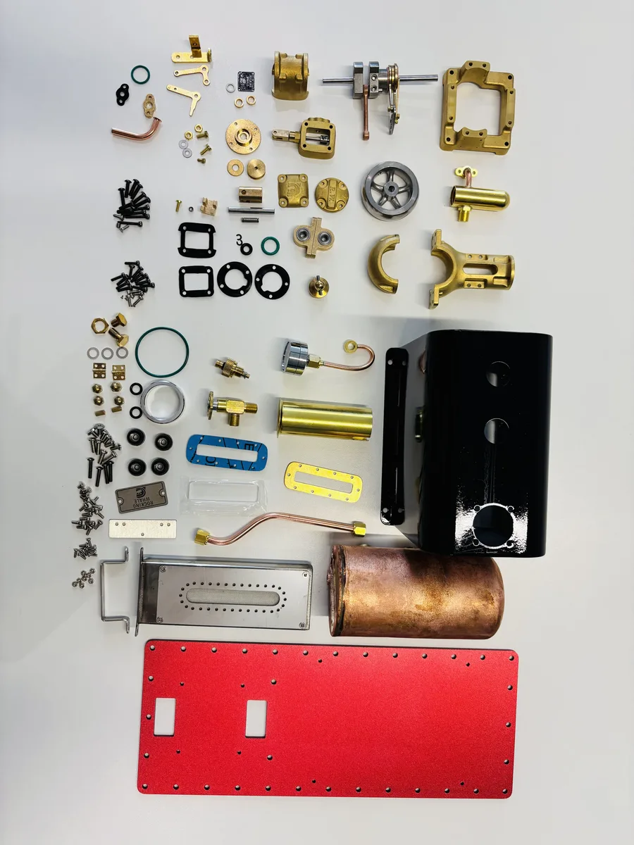
The Rocking Whale BL1K combines a die-cast brass engine structure, a brass cylinder with stainless-steel liner, a ball-bearing-supported crankshaft and complete Stephenson reversing gear. Its boiler has a copper-welded body and is fitted with a pressure-regulating valve, safety valve, pressure gauge, water-level gauge and vaporised-alcohol burner.
The manual identifies a 3 cc engine specified at 3000 RPM and 0.015 HP, a 200 ml boiler and a 30 ml alcohol (≥95% purity) fuel capacity. Its normal engine working range is 0.5–2 bar; engine pressure must not exceed 3 bar. These are operating limits for this documented model, not general boiler design values.
Operational practice
Water, heat and controlled operation
Before firing, fill with clean water only to the stated maximum indicated by the water-level gauge, verify that the pressure-regulating valve moves freely, and check that the safety valve lifts and reseats smoothly. Water level must remain within the gauge range during operation. Once boiler pressure reaches 2 bar, open the pressure-regulating admission valve in small increments to supply steam to the engine; the manual identifies this valve as quick-opening.
The manual calls for steam oil in the oil tank and oil on rotating and sliding parts before operation, with accumulated water drained from the tank beforehand. It specifies approximately one hour of running-in below 2000 RPM, a 3000 RPM maximum working speed, and reduced speed before reversing. If the engine stops at dead centre, move the flywheel off that position before steam can produce torque; any use of the documented reversing-lever technique is a BL1K-specific operating procedure, not a general dead-centre remedy. Hot surfaces and discharged steam require cooling time, gloves and eye protection.
Documented figures
Model-specific specifications.
| Specification | Documented value |
|---|---|
| Engine displacement | 3 cc (1.5 cc × 2) |
| Engine speed limit | 3000 RPM |
| Maximum torque | 600 gf·cm |
| Power | 0.015 HP |
| Normal engine working pressure | 0.5–2 bar |
| Maximum engine working pressure | 3 bar |
| Boiler water capacity | 200 ml |
| Alcohol fuel capacity | 30 ml alcohol (≥95% purity) |
Editorial sources
References & further reading
- The Newcomen Steam-Atmospheric Engine American Society of Mechanical Engineers Open source
- Boulton & Watt Rotative Steam Engine American Society of Mechanical Engineers Open source
Engineering tools & resources
Comparing engine configurations? Explore the Model Steam Engine Comparison Guide. Evaluating hull propulsion? Use the interactive Model Boat Steam Engine Size Calculator.